Roomba Replacement Parts: Safe Basics for Removing and Installing Common Components
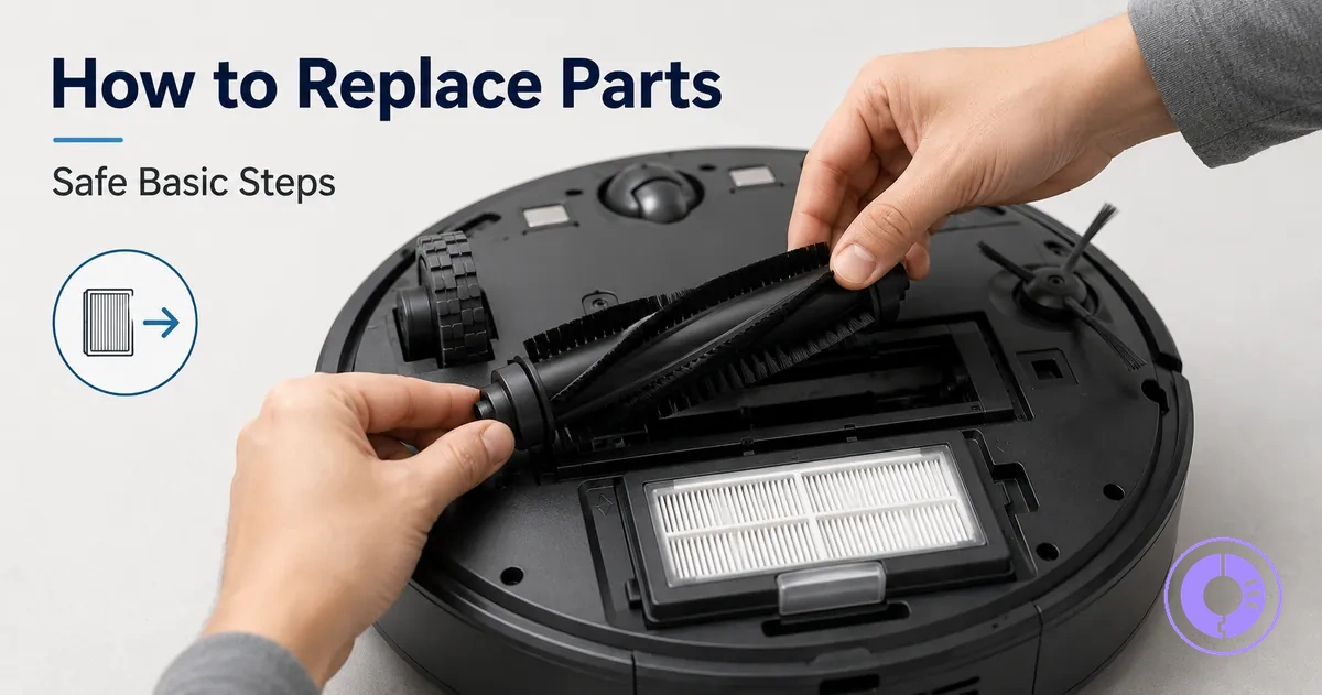
A safe baseline method for replacing common Roomba parts helps prevent damage and post-swap errors. Steps and outcomes vary by model and part type. The focus is on repeatable behaviors rather than model-specific instructions.
Common mistakes include forcing components into place or damaging clips during removal. Before removing any part, verify compatibility with your Roomba model; proper fitment reduces the risk of operational issues.
Replacement part scope for this basic process and where model-specific steps begin
This basic process covers common user-serviceable swaps, while access steps can vary by model.
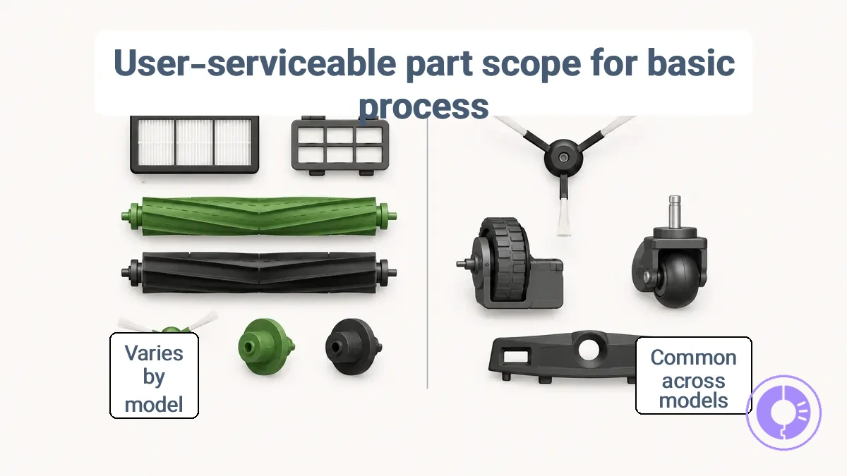
User-serviceable swaps are parts that can be replaced without full disassembly, usually secured with screws or clips. For a broader overview of available part categories, visit the Roomba replacement parts hub. Before loosening any screw or clip, identify parts using a diagram to help confirm the correct component.
Unusual resistance or inability to see the attachment may indicate a stop condition that should not be forced.
Replacement part scope for this process includes two categories:
- Fits the basic process – Parts such as filter covers, debris extractors, and roller end caps typically follow similar removal steps across models.
- Requires model-specific guidance – Parts such as side brush assemblies, wheel modules, and battery compartments may differ in access method and need extra verification.
Power-off safety and handling rules before opening the robot or removing parts
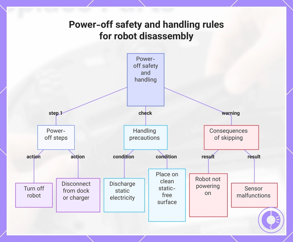
Before opening the robot or removing any part, turn off the power and disconnect it from the dock or charger.
Turning off the power and disconnecting prevent electrical shock, accidental startup, and damage to sensitive components. Skipping these steps may cause errors after reassembly, such as the robot not powering on correctly or sensors malfunctioning.
Use these power-off and handling rules to verify safe starting conditions for disassembly:
- Turn off the robot using its power button or switch.
- Remove the robot from its dock or unplug the charging cable.
- Wait a moment for internal stored energy to dissipate.
- Place the robot on a clean, dry, static-free surface.
- Discharge static electricity by touching a grounded metal object before handling internal parts.
- Handle connectors and wiring carefully, and check for any damage before proceeding.
- If the robot was recently running or is still connected to the charger, its components may be warm or tightly seated; let it cool and inspect before handling.
This chart shows the essential power-off steps, handling precautions, and risks of skipping these steps before opening or removing parts from a robot.
Tools and fastener handling that prevent stripped screws, broken clips, and mis-seated parts
Using the right tools and handling during removal and reinstallation helps prevent stripped screws, cracked clips, and mis-seated connectors.
Fasteners, clips, and connectors each have different release mechanisms and require specific handling to avoid damage. The approach that works for a screw can break a plastic clip, and the force used on a clip can bend a connector pin. The rule is simple: match the tool to the attachment.
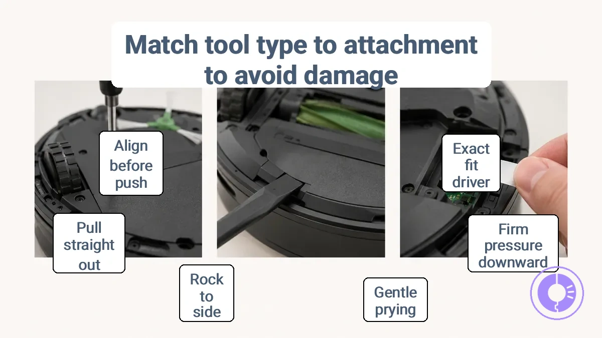
Tools and fastener handling relies on recognising the attachment type and applying the right technique. The image labels the attachment types and shows safe handling direction. This checklist groups common tool and handling habits by attachment type to help you avoid stripping, cracking, or mis-seating.
- Fasteners
- Use a screwdriver or driver bit that fits the screw head shape and size exactly; a loose fit often strips the slot. (Right-size driver vs rounded head risk.)
- Apply firm downward pressure while turning to keep the driver engaged; slipping can round the head edges and make removal harder.
- Clips
- Pry plastic clips gently with a flat spudger or tool at the designated release point; forceful prying may crack the clip or its mounting tab.
- If a clip resists, rock it side to side instead of pulling straight up; this reduces stress on the latch and helps release without breakage.
- Connectors
- Pull ribbon or wire connectors straight out from their sockets after releasing any locking latch; twisting or angling can bend pins or damage contacts.
- Align the connector with the socket before pushing it in; misalignment may cause bent contacts or an incomplete seated connection.
- On ZIF (zero insertion force) connectors, lift the latch before inserting or removing the cable; forcing the cable under a closed latch can damage the contacts.
Avoid forcing any fastener or attachment beyond its intended release; over-tightening screws can strip threads, and prying clips too hard can snap them. A mis-seated connector often produces a loose fit or intermittent signal—check alignment if the symptom appears.
Compatibility checks that prevent wrong-fit installs and repeated error states
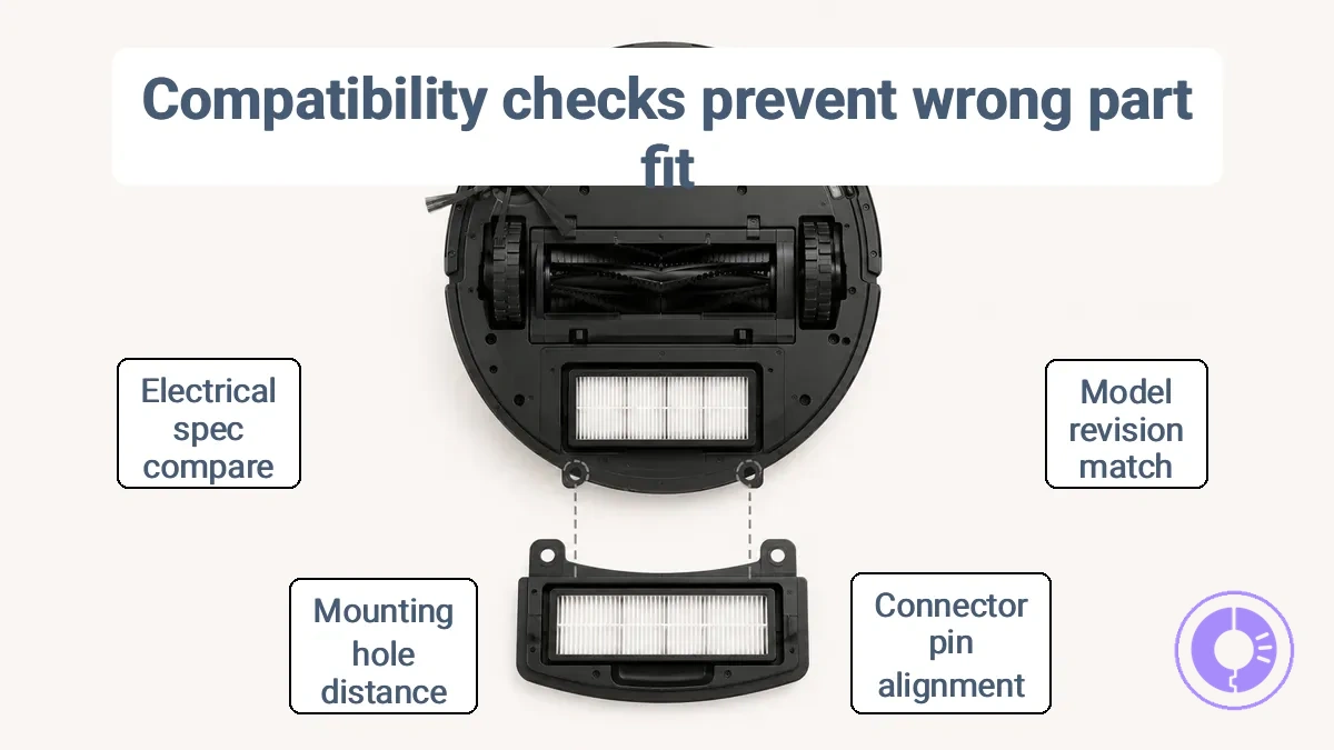
Compatibility checks prevent wrong-fit installs and repeated error states when replacing parts.
A part that looks similar may not match the required connector, mounting points, or part revision.
Check the model identifier, part revision, and connector type to confirm fit. The table organizes compatibility checks by model cue and fit risk.
| Model cue | Part cue | What to verify | What a mismatch can cause |
|---|---|---|---|
| Model number | Part revision | Match original part's model and revision | May cause connection failure or repeated error state |
| Connector shape | Pin arrangement or fitting depth | Visual alignment and insertion depth | May cause loose connection or intermittent error |
| Mounting hole spacing | Bracket or screw pattern | Measure distance between holes | Part may not be secured, leading to movement and error |
| Electrical specification | Wire gauge or terminal type | Compare with original part label | May cause electrical fault or component damage |
| Software version | Firmware revision | Check compatibility list from manufacturer | May cause communication error or system instability |
| Color or material | Visual finish | Ensure same material type for intended use | May cause premature wear or reduced performance |
Do not install the part if any of these cues do not match; verify the correct part instead.
The Basic Replacement Sequence: Remove, Inspect, Install, and Verify
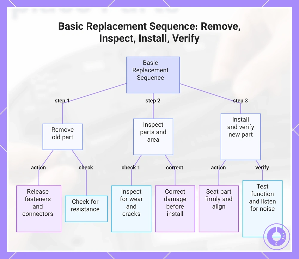
The basic sequence for safe part replacement is remove, inspect, install, and verify.
Following this order prevents rework and catches damage; the steps that follow include checks and stop-and-correct signals at each stage.
- Remove the old part — release all fasteners, connectors, or clips. Check for resistance. If the part does not come free with normal effort, stop and confirm the correct removal method before continuing.
- Inspect the part and mounting area — look for wear, cracks, debris, or misalignment. If damage is visible or the surface is not clean, correct the condition before installing a replacement.
- Install the new part — seat it firmly and align mounting points. Check that it fits evenly without gaps. If it resists or sits crooked, stop and recheck alignment before tightening.
- Verify operation — test the part's movement or function. Listen for noise, binding, or unusual symptoms. If any symptom appears, stop and repeat inspection and installation steps.
Do not skip the inspection stage before installation; a quick check can prevent damage that would require repeating the entire sequence.
This chart shows the four main steps of the safe part replacement process, including key checks and corrective actions at each stage.
Removing the old part without damaging housings, connectors, or mounts
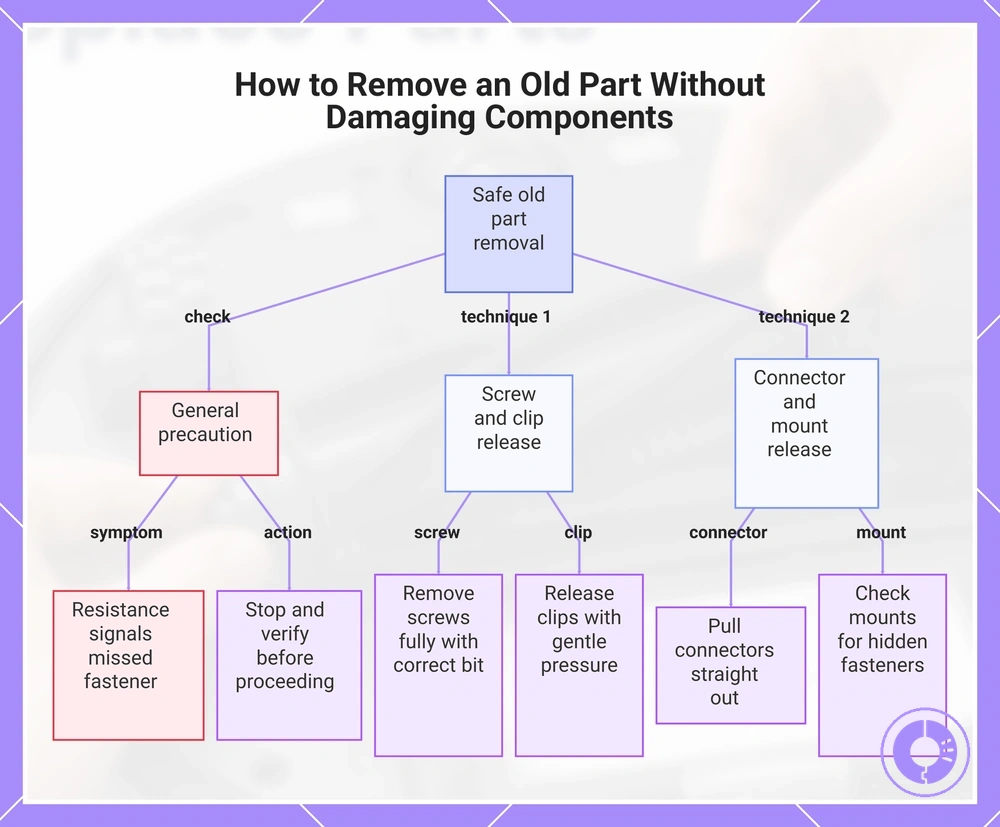
Identify the attachment method — screw, clip, or connector — to remove the part without damaging housings, mounts, or connectors. Resistance often signals a missed fastener or a misaligned clip, so stop and verify before proceeding.
Removing the old part safely means matching each attachment type to its correct release technique:
- Screws: remove fully with the correct bit; do not pry against the housing.
- Clips: release the latch or tab with gentle pressure; avoid twisting or pulling at an angle.
- Connectors: pull straight out from the mount; rocking or angling can crack the plastic housing.
- Mounts: check for hidden fasteners or adhesive before lifting the part.
This chart shows the correct techniques for removing a part based on its attachment method, along with a key warning to check for resistance.
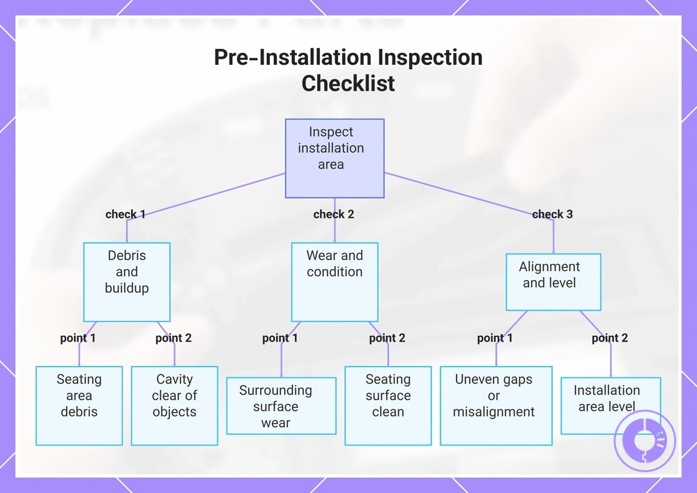
Inspecting the Area for Debris, Wear, and Alignment Cues Before Installing the New Part
Before installing the new part, inspect the area for debris, wear, and alignment cues to prevent fit or performance issues. Skipping this step can cause immediate problems like poor seating, noise, or restricted movement. Focus on the seating area, cavity, and mounting points since these directly affect fit and movement. The checklist below covers what to check and how each factor impacts installation success.
- Inspect the seating area for debris or buildup that could prevent a flush fit.
- Check for visible wear on surrounding surfaces that may indicate alignment problems.
- Look for alignment cues such as uneven gaps or misaligned mounting points.
- Verify that the seating surface is clean and free of residue; clean it before install if needed.
- Confirm that the cavity is clear of foreign objects that could block movement or airflow.
- Check that the installation area is level.
If the part requires a flush fit, cleaning the seating surface can help prevent noise or misalignment.
This chart shows the three main inspection categories—debris, wear, and alignment—and the specific checks to perform before installing a new part to prevent fit issues.
Seating the new part correctly using orientation and fit cues
Seating a replacement part means using orientation cues to align it, so it sits flush and stable with only a light press — no force required.
To seat the new part correctly, check observable fit cues that confirm orientation and help avoid partial seating:
- Directional marks or logos: sits flush and does not rock. Symptom if reversed: may tilt or fail to lock.
- Notches or keyed shapes: slides into position without binding. Symptom if misaligned: may feel loose or require excessive pressure.
- Text or arrows: level and stable when lightly pressed. Symptom if reversed: may protrude or interfere with adjacent components.
After seating, re-check by gently wiggling the part; it should remain stable and not shift.
If any symptom of partial seating appears, remove the part, verify its orientation, and reseat.
Post-install verification: movement checks, airflow checks, and a short test run
Post-install verification confirms the swap works before a full run, catching issues like restricted airflow or misaligned parts early to prevent wasted time and damage. This checklist organizes simple physical checks to validate movement, airflow, and basic operation in minutes.
Use these checks in order; if you see any abnormal sign, stop and re-check the likely installation cause:
- Movement check — move dampers, registers, or any newly installed parts. Smooth travel without binding or drag indicates proper alignment; resistance or misalignment means re-checking bracket alignment and fastener tightness, since improper seating is a common installation-linked cause.
- Supply vent airflow — feel for steady air movement at each open supply register. Consistent flow across all vents is expected; a weak or missing air supply means re-checking duct connections and filter seating—a blocked or pinched duct may be the cause.
- Return grille suction — place a paper or hand against the grille to gauge draw. Light suction that holds the paper is normal; weak suction means re-checking filter orientation and return plenum for obstructions, as installation-linked restrictions are a frequent cause.
- Short test run — turn the system on for a brief cycle (3–5 minutes). Expect smooth startup, stable airflow, and no unusual sounds. Rattling, vibration, or uneven airflow indicates a problem; stop the system and re-seat any loose panels or mounts before proceeding.
Applying the basic process to common swaps without turning each part into a full procedure
The same basic process works across common swaps.
What may change is the specific access route, the part design, and the risk points during installation.
For example, swapping a battery, a brush module, or a wheel assembly may follow the same sequence but differ in how you reach the part and what can go wrong. Common swaps include battery group, brush assembly, wheel unit, and filter set.
The table below applies the basic process to common swaps and maps each part family to its access difference, key risk, and best quick check.
| Part family | What changes | Key risk | Best quick check |
|---|---|---|---|
| Battery assembly | Access path (bottom panel or side opening) | Connector damage or wire pinching | Power-on and charging test |
| Brush module | Mounting method (screw or clip) | Sealing or alignment failure | Run cycle and listen for noise |
| Wheel assembly | Wiring harness routing | Cable strain or connector damage | Roll test and check movement |
| Filter set | Retention mechanism (tab or latch) | Incomplete seal | Check fit and run short test |
Deciding when to perform a swap is a maintenance decision separate from the installation method; refer to the replacement schedule to time swaps.
Detailed part-specific sequences belong in dedicated pages when exact access steps are required.
Filter swaps that avoid airflow leaks, bypass, and loose seating
When swapping filters, avoid airflow leaks and loose seating by starting with a tight fit in the cavity. Even a small gap around the filter frame can let unfiltered air bypass the media, which can reduce suction and may pull debris into the system. These steps help achieve a snug fit and prevent bypass.
A snug fit depends on both the filter edges and a clean cavity.
- Turn off the system before removing the old filter to avoid drawing unfiltered air into the blower.
- Inspect the cavity for dust or debris that could prevent a flush seal, and clean it if needed.
- Insert the new filter with the airflow arrow pointing toward the blower or fan.
- Check for gaps along all edges; the filter should not shift when touched.
- After closing the access panel, listen for rattling or whistling sounds that indicate a seal problem.
If the filter still seems loose or airflow is poor, debris trapped in the cavity can mimic a failed filter, so re-check the housing for obstructions. For model-specific access steps, see the replace filters guide.
Brush and roller swaps that avoid tangles, wrong-side placement, and drive strain
Correct orientation and seating prevent tangles, wrong-side placement, and drive strain when swapping brushes or rollers. Two common mistakes are installing a brush or roller upside down or forcing a component that does not rotate freely.
Checking orientation, clearing debris, and seating the end caps fully are the keys to avoiding tangles and drive strain.
- Check orientation before insertion. Align the brush or roller so its end matches the socket shape; wrong-side placement often feels tight or crooked.
- Spin the component by hand after seating. A smooth rotation feel indicates correct alignment; resistance or grinding suggests misplacement.
- Remove visible debris from the housing. Tangles often start when hair or string wraps around the brush bar during the first rotation.
- Seat both end caps fully. Loose end caps can cause noise and drag immediately after the swap.
- Verify the brush or roller spins without binding. If it stops or stutters, recheck orientation and debris clearance.
Your model's instructions provide the exact steps to replace brushes and rollers.
Battery swaps that avoid connector damage and first-charge setup mistakes
Replace the battery without stressing the connectors and complete a safe first-charge setup to help maintain reliable contact and early performance. Gentle handling reduces stress on the connector housing and helps ensure the connection stays secure.
Seat the battery firmly and verify the initial recharge with these steps:
- Do: Inspect the battery compartment for debris and corrosion. Verify: Clean any buildup from the terminals before connecting.
- Do: Line up the connector with the matching notch. Verify: The connector is fully seated until you hear or feel a click.
- Do: Use a wrench on the terminal nuts only until snug. Verify: The cables do not wobble when tugged gently.
- Do: Attach the correct charger for the battery type. Verify: The first recharge completes without interruption or error codes.
If the device does not power on after reassembly, a loose connector can cause poor contact and mimic a failed battery even when the battery is new. For complete safety guidance, refer to how to replace the battery safely.
Wheel module swaps that avoid alignment issues and poor traction after installation
Wheel module swaps that prevent alignment issues and poor traction start with proper seating. A poorly seated module can cause pulling or stuttering.
- Begin by cleaning the wheel well and removing any debris that could prevent the module from sitting flush.
- Seat the module firmly against the mounting surface, then tighten the fasteners in a crisscross pattern to the torque specified for your model.
- Rotate the wheel by hand to confirm smooth movement and check for binding.
- After a short test drive, re-check the seating and inspect the wheel well for debris before assuming the module is defective.
For model-specific details on maintaining grip and straight tracking, see wheel and traction replacements.
Common replacement mistakes that cause noise, poor cleaning, or recurring errors
Post-replacement problems such as noise, poor cleaning, or recurring errors are usually caused by seating, orientation, debris, or mismatched parts.
When a symptom appears after a replacement, checking the installation first is faster than assuming the part is defective. Start by looking at how the part sits, alignment, and debris.
Common replacement mistakes produce specific symptoms. The list below matches each symptom to its likely cause and the fastest re-check action:
- Mis-seated part → noise or vibration → Remove the part and reseat it firmly.
- Incorrect orientation → poor cleaning or performance → Verify alignment marks or directional indicators.
- Debris in the cavity → drag, resistance, or clicking → Clean the area thoroughly before reinstalling.
- Mismatched replacement part → recurring errors or poor function → Compare the part to the original in shape, size, and mounting points.
- Over-tightened fasteners → binding or grinding → Loosen to the correct torque and retighten.
- Under-tightened fasteners → looseness or rattling → Tighten to the recommended specification.
- Using an incorrect tool → damaged part or housing → Switch to the proper tool and inspect for damage.
- Failure to remove protective covers → blocked airflow or poor cleaning → Remove all packaging and covers before installation.
- Dirty mating surfaces → poor seal or intermittent noise → Clean both surfaces with a dry cloth before reassembly.
If the part does not match the original in any way, stop installation and confirm compatibility before continuing.
A mis-seated part may produce a clicking sound that disappears after reseating, while a mismatched part often causes the same error to return. Pre-existing wear in surrounding components can sometimes mimic an installation mistake. In both situations, re-check fit before assuming failure.
This chart shows the most common installation mistakes that cause post-replacement problems, grouped by cause type, and the recommended actions.